Overview
A few years back I had the seemingly bright idea to build a privacy device for Amazon Echo users. I even managed to secure a utility patent for my invention: US Patent 20190371339A1. The idea was pretty simple. We called it BuzzOff.
BuzzOff was essentially a specialized IOT power switch that would control the power to your Amazon Echo device. And you could actually control it using an Alexa skill. Just say “Alexa go away for 5 minutes” and that would send a command to the BuzzOff device, which would cut the power to that Echo device–or to ALL of the Echo devices in your house. Then a built-in timer would turn the power back on at the specified time. We built a custom ESP32 based PCB to implement BuzzOff.
The solution worked brilliantly, but alas the product was a failure. People said they wanted privacy, but when the time came, didn’t want to sell out some cheddar for a BuzzOff. So that startup failed and now I have a bunch of BuzzOff PCBs in my basement. My loss can be your gain though, as I am selling the surplus stock for bargain prices. This can be a cheap way for you to experiment with ESP32 or maybe even use them in some custom project of your own, like maybe a remote switch for your Amazon Echo devices?
Two flavors: DC or USB powered
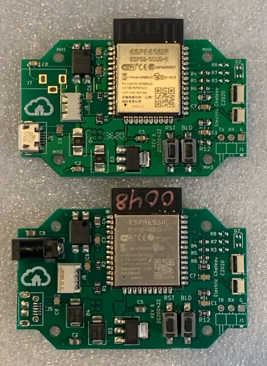
Since Echo devices came either as micro USB powered or powered by a DC barrel connector, there are two versions of the BuzzOff PCB. It’s actually a single master design for both PCBs, but the boards are populated differently for USB vs DC barrel connector.
Tech Specs
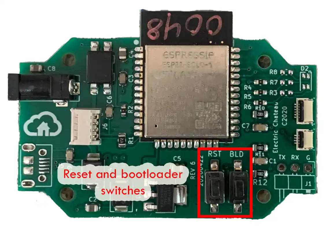
All BuzzOff PCBs are powered by the ESP32-SOLO-1 from Espressif. All PCBs have power in, relay controlled power out, 4 pin connector for a membrane switch, 6 pin connector for an RGB LED daughterboard and pushbuttons for reset and bootload. The important parts are listed below. The part number for the DC barrel connector listed below will only be populated on DC variants.
| Designator | Part | Description |
|---|---|---|
| U1 | Espressif ESP32-SOLO-1 | Bluetooth/WiFi SOC |
| U2 | MaxLinear SPX1117M3-L-3-3/TR | 3.3V 800mA regulator |
| U3 | Panasonic AQY211EHA | Solid State Relay 30V 1A |
| J2 | TE Connectivity 2328702-6 | 6 pin 0.5mm FFC Connector |
| J3 | TE Connectivity 2328702-4 | 4 pin 0.5mm FFC Connector |
| J6 | Molex 53048-0410 | 4 pin 1.25mm TH JST Connector |
| J7 | CUI Devices PJ-031DH | DC barrel Connector for 3.5x1.3mm plug |
Powering your BuzzOff PCB
The PCBs are desgned to run off the power supply that comes with an Amazon Echo device. For the USB boards, this is a typical micro USB power supply.
For the barrel connector boards, this is a DC power supply. Note that the barrel connector may not exactly fit an Amazon Echo power supply. This is because all of Amazon’s power connectors were proprietary. We developed adapters that adapt Amazon’s power supply connector to a standard barrel connector (and vice versa). I will throw some of these adapters in with the barrel connector versions, as long as supplies last.
As to the input voltages that work, anything from 5 to 15V has been tested, as we supported a wide range of Echo products.
RGB Daughterboard
Each BuzzOff PCB has two FFC connectors, shown in the photo below.
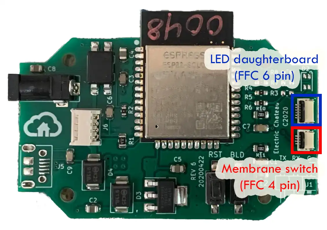
The 6 pin FFC connector is for connecting to the RGB daughterboard that was the status indicator for BuzzOff. Each BuzzOff PCB will come with a 6 pin FFC cable and an LED daughterboard with a tri-color super-bright LED. Here’s a photo of the LED board. The FFC connector is on the reverse side of the board.
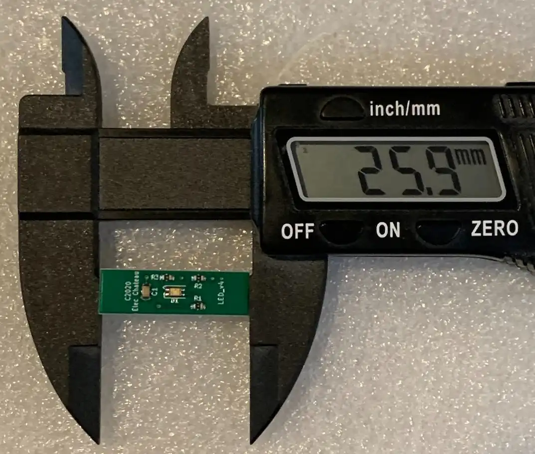
I haven’t been able to locate the spec for the LED FFC connector, but to the best of my knowledge it is as follows. I’ll edit this description with definitive information when I find it.
| Pin | ESP32 Pin | Description |
|---|---|---|
| 1 | DIO 26 | LED red |
| 2 | GND | GND |
| 3 | DIO 27 | LED green |
| 4 | GND | GND |
| 5 | DIO 14 | LED blue |
| 6 | GND | GND |
Membrane Switch connector
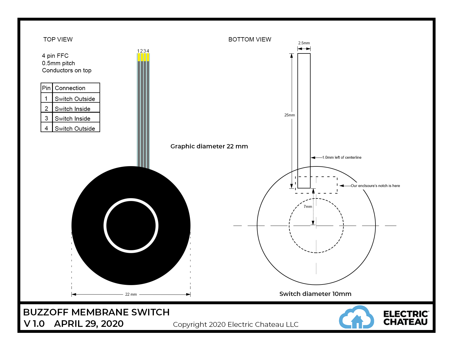
The 4 pin FFC connector was for connecting to a membrane switch. The membrane switch is not included, but here’s a specification of the wiring for the connector. The pins are wired to DIO 5 on the ESP-32.
Controlling a DC load
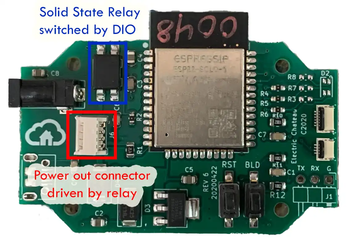
BuzzOff was designed to switch an Amazon Echo on and off, so it has a built-in solid-state relay that is controlled by DIO 33 on the ESP-32. The relay outputs are wired to the 4 pin JST connector shown below.
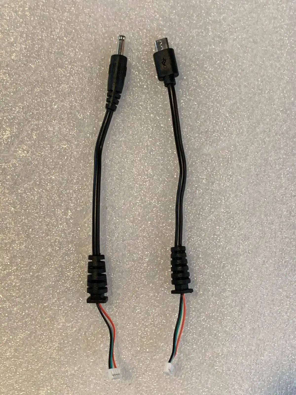
Each BuzzOff PCB will also come with a power-out “pigtail cable” that plugs into the JST. USB boards come with a micro USB pigtail. DC boards come with a DC barrel plug pigtail. The pigtails are about 4 inches long. The pigtails have a molded strain relief in them. Here’s what the two pigtails look like:
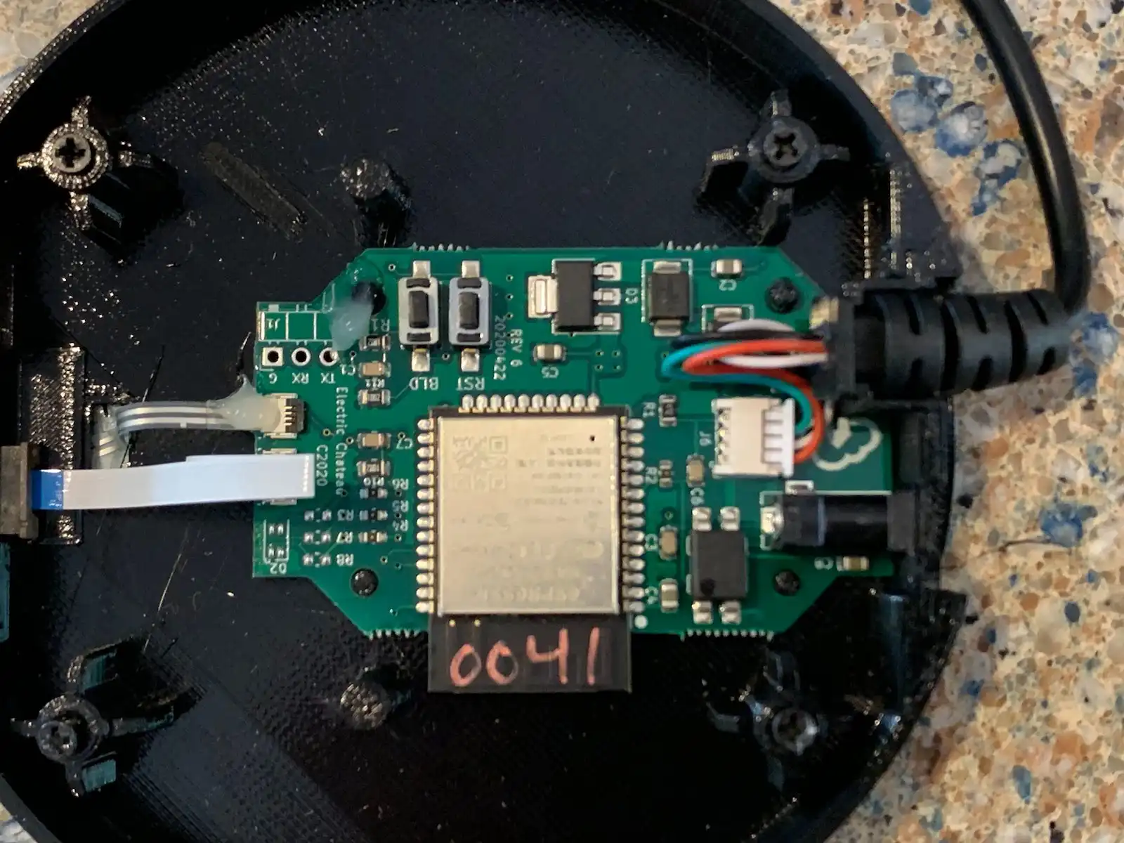
Here’s a photo of one plugged into an assembled BuzzOff device.
Check the datasheet for the Panasonic relay for absolute tech specs, but anything up to 1 Amp should work. The output voltage of the pigtail is simply whatever the input voltage is that you supplied.
Programming
Programming is accomplished through the 3 holes highlighted below. The onboard USB connector on USB versions is NOT CONNECTED to the programming pins. It is for power only. To program the board, you must supply power to your board, either via USB or DC barrel connector.
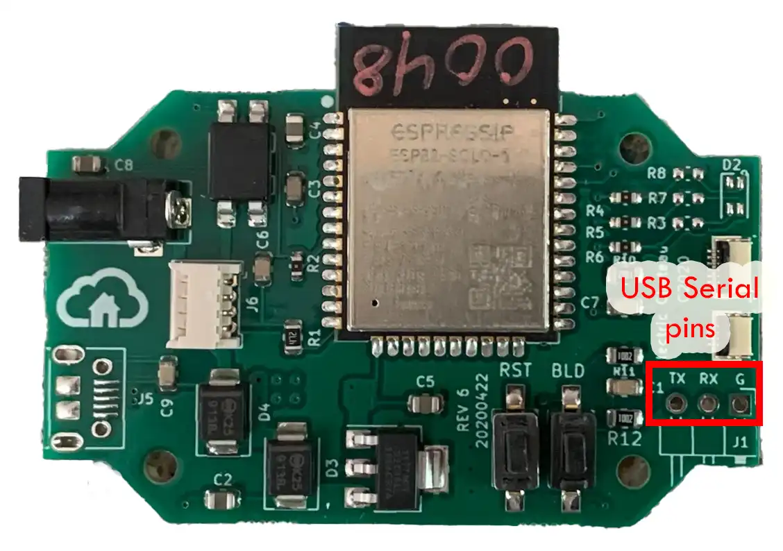
You will also need a USB to TTL adapter with 3.3V support. I use something like this HiLetGo USB TTL Adapter. Just connect RX/TX and GND from the adapter to the those three holes. Be sure to set the adapter to 3.3V using the jumper. If the USB TTL adapter is set to 5V, you risk frying the ESP-32!
You can solder a pin header to the PCB to make it easier to connect the USB TTL adapter, or you can simply hold the pins in place with your hand while programming.
After connecting the adapter, start your firmware download process and then hold Bootload button down. Then press and release Reset. The release bootload.
Warranty
There is no warranty of any sort on these boards. They were factory tested and in our testing, we had no failures. They have been stored in a climate controlled environment and hopefully they’ll work for you.
How To Support Me
Please check out Waddle Waddle, my penguin-themed tabletop game that's perfect for family game night. It's both fun AND educational. It's filled with dozens of great photos of penguins that I took while in Antarctica. It plays 2-6 players and is great for players 9 and up.
My designs are all designed to minimize filament usage, and that directly saves you MONEY, and many hours of print time. Most of these designs take two or three generations to perfect. You can show your thanks for me saving you money and many HOURS of your time making by a small donation to defray the cost of professional software licenses, printer wear and tear, and the filament I use to develop this content for you:
As an Amazon Associate I earn from qualifying purchases. By purchasing the products that I recommend through affiliate links you directly support the creation of more great content at no cost to yourself. I only recommend products that I use myself. You can read more about it here: Affiliate disclosure.